
Compliant Electromagnetic Actuation
Industrial robots often need actuators to be as stiff as possible for placement speed, accuracy, and to generate high force. With robotics now moving into applications that require greater adaptability for handling soft or fragile materials and to avoid injury when working with humans, robots increasingly require the use of variable stiffness actuators (VSA) or adjustable compliance actuators. With standard actuator technology this is typically realized with series elastic elements such as springs to absorb shock and store energy however series elastic actuation increases system complexity and inertia. When the stored energy is suddenly released, it can result in high speed motion of the robot, and a correspondingly high risk for humans in case of collision. Reducing this risk usually requires complex mechanisms or sophisticated control systems. Active Signal Technologies has developed a linear electromagnetic actuator that performs as an electrically adjustable linear spring, or adjustable compliance actuator. This new actuator technology is bidirectional, inherently compliant, inherently damping, and eliminates the problem of any sudden release of stored energy. The reason for this is that although the actuator behaves as a constant force spring it does not store mechanical energy. The force from this actuator is linear and controllable from zero to the mechanical limit of the actuator. This actuator is also fast and can respond to control input within 20ms typically. The actuator’s force does not vary over the actuation range and it is non-latching. This new technology is also smaller and lighter than traditional moving coil, moving magnet or moving iron linear actuator technologies with equivalent force performance. For example, one of the actuators described here is 3 inches long, 3 inches in diameter, weighs 4.6 pounds and can generate forces from zero to 160+ pounds with a frequency response of 85 Hertz. The force generated by this actuator technology is not limited by magnetic field saturation, it is only limited by the mechanical strength of the actuator.
This new actuator technology has the following attributes:
• Linear force:
Force increases linearly with applied drive current.
Force is constant across the actuation distance for a fixed drive current.
• Bidirectional drive:
This actuator is fully bidirectional with equal force, speed and displacement parameters in either direction. Simply by reversing the polarity of the drive current.
• Compliant actuation:
The force generated by this actuator is constant across the actuation distance for a fixed drive current. This force is linearly adjustable by varying the drive current. The device is therefore an adaptable or adjustable compliance actuator. When power is removed all actuation forces are also removed and the device becomes totally and passively compliant. This actuator contains no springs, elastic components, or complex mechanisms to create compliance. Compliant behavior is inherent in the constant force delivered at a constant drive current and does not require a feedback loop.
• High speed:
The frequency response of this new device is wider than available with most linear electromagnetic actuation technologies and can be as high as 500Hz, depending on the size and design of the actuator, but typically is above 50Hz. The frequency response is constant across the actuation distance but due to the variable stiffness of the actuator the frequency response can be made to vary with load and drive current. Because of this effect the frequency response can go up as the drive or stiffness of the actuator goes up. Tradeoffs can be made in the design of the actuator to maximize performance for high force or wide frequency response.
• Long actuation distance:
Actuators have been modeled with actuation distances of up to 5.08 cm (2 inches) for devices with an OD (outside housing diameter) of 7.62 cm (3 inches).
• High force:
This actuator is capable of intermittent high force which can be applied at any point along the actuation distance. Generation of high forces must be limited to shorter time durations due to internal heating. The primary limits to the force capability of this actuator are thermal dissipation and structural integrity. It is possible to generate forces high enough to mechanically damage the actuator.
• Self contained:
The mechanical actuation component and magnetic fields are contained within the device, with little to no field leakage outside the device.
• Scaleable:
Actuators can be designed to have multiple actuation stages within a single device which add forces algebraically. Since each pair of stages share a common element internally this makes the overall device shorter than if it were separate actuators mechanically in series. Also, because all of the stages in this type of actuator operate independently it is possible to fine tune the actuation forces by controlling how much drive current is applied to each section independently. All non powered stages within a multiple stage actuator will neither add to or subtract from the total force output from the actuator.
• Compliant failure mode:
If an actuator should fail or if the drive power is removed the actuator will become limp or totally compliant. It inherently has no jamming failure mode. This actuator requires no springs, elastic components, or other complex mechanisms to invoke this graceful failure mechanism.
• Non latching:
This actuator has no latch up or other nonlinearity at any point along the actuation distance. The actuation force is constant from stop to stop for a fixed drive current.
• Passive damping:
Passive damping is an inherent capability of this actuator. By applying a short or an electrical load to the actuators electrical drive connection the motion of the actuator can be damped. This damping is bidirectional and acts equally across the actuation distance. However the amount of passive damping can be adjusted through appropriate design of the actuator.
• Rotary motion:
This actuator technology is inherently linear but rotary device designs have been explored that allow motion up to ±45°. The rotary versions retain many of the capabilities of the linear version.
• Configurable force profile:
This actuator design is intended primarily to have a constant force/distance/drive profile, however the same technology also allows the force/distance/drive profile to be engineered to conform to a nonlinear profile. This profile can be adjusted in the design of the device to create force variations (within reason) anywhere along the actuation distance. This profile then becomes inherent to the actuator.
• Manufacturability:
Manufacture of this actuator is straightforward due to simplicity of design. The part count is low and high permeability materials are not required. In addition it does not require finely toleranced magnetic gaps, and is relatively insensitive to misalignment of the internal magnetic elements.
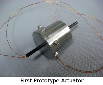
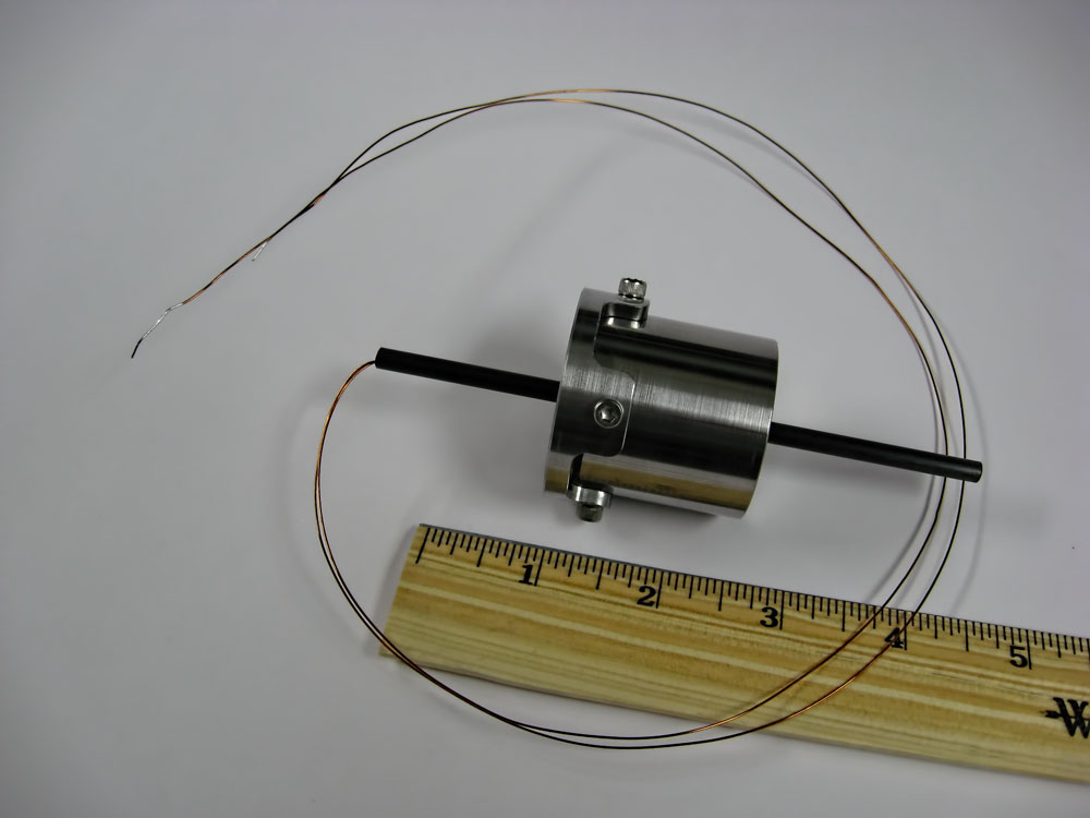
A first prototype proof of principal device was constructed from dimensions and materials derived from finite element magnetic modeling. This device (pictured below) is a 0.295kg (0.650lb), 4.1cm (1.61in) long (not including output shaft), 3.8cm (1.49in) diameter device with a bi-directional symmetrical actuation distance of 1cm (0.393in). It has a continuous force output rating up to 8N (1.79lbf) and an impulse rating of 55N (12.36lbf) (<150ms pulse repeated at >2 second intervals) with a frequency response of 150Hz. Force/Amp is 0.7lbf (3.11N). The shell is constructed from 416 Stainless Steel and it has a pultruded carbon composite tube to transfer the actuation forces from within the device. The performance of this device was measured and compared to the modeled data.
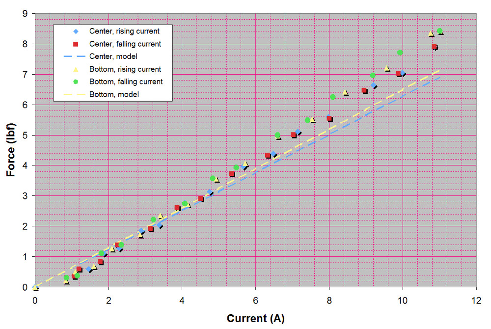
As you can see from this force versus current graph (above), the force output from the real device actually exceeded the model predictions slightly. The different positions, "Bottom" and "Center" refer to the position of the actuator within its travel distance to compare the forces at the center of travel to those at one end of travel. This test measured the blocked force of the actuator.
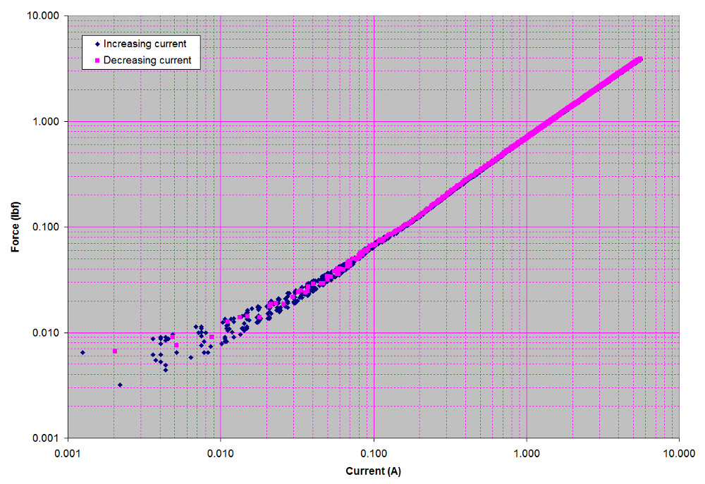
In this force resolution range plot (above) you can see that although the device can be controlled down to zero force, the noise floor of the instrumentation did not allow good resolution of the forces below .044N (0.01lbf), but this shows that the force / current relationship is indeed linear. This test measured the blocked force at the center of the actuation distance.
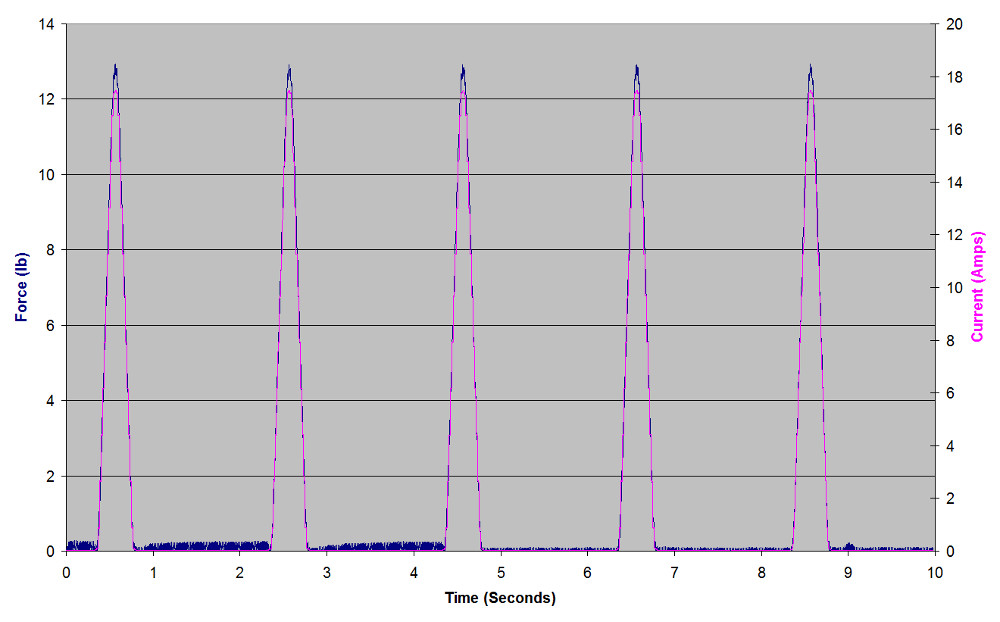
This plot (above) shows the results of an impulse test which measured the blocked force at the center of the actuation distance while driving the actuator with a slightly rounded triangular current waveform. Note that the measured actuator force very closely follows the drive current waveform.
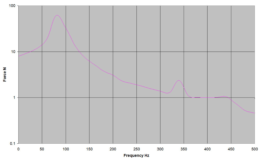
The actuator was driven with a constant amplitude electrical input while using a 22 pound inch spring for a mechanical load as the drive frequency was swept from 0Hz to 500Hz with the resulting force being measured with a load cell. The frequency response plot of the actuator (above) is quite good and shows a single peak at about 70Hz which is the resonance of the load spring and the mass of the actuator. This single peak shows that the actuator has a simple resonance with no complicated overtones. The smaller peak at about 340Hz is the self resonance of the spring that is being used as a load. Because this actuator has variable stiffness, the frequency response can change with change in drive current. The result is that the frequency response can go up or down as drive current increases or decreases.
Since the construction and testing of this prototype, improvements have been made to enhance the overall performance of this type of actuator. A second generation device was constructed, as pictured here in this 3D CAD image.
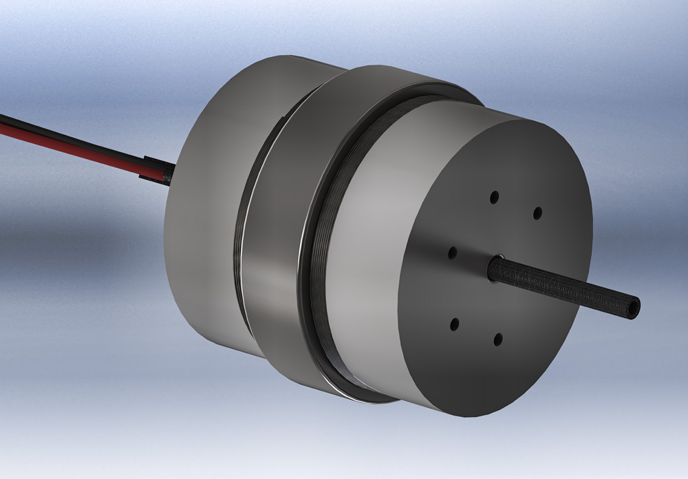
This new actuator has been optimized for maximum force performance at the expense of frequency response. The modeled capabilities are as follows:
Length: 3.0in (7.62cm)
Diameter: 3.28in (8.33cm)
Weight: 4.76lb (2.16kg)
Actuation distance: 0.590in (1.5cm)
Frequency response: 80Hz
Force/Amp: 5.45lbf (24.266N)
Continuous duty rating: 5A, 27.2lbf (120.99N)
Intermittent duty rating: 40A, 214.27lbf (953.15N) (<150ms pulse repeated at >2 second intervals)
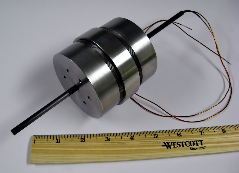
The 3 inch actuator prototype (pictured above) has been completed and the measured capabilities are as follows:
Length: 3.038in (7.71cm)
Diameter: 3.23in (8.20cm)
Weight: 4.62lb (2.09kg)
Actuation distance: 0.553in (1.4cm)
Frequency response: 85Hz
Force/Amp: 4.44lbf (19.75N)
Continuous duty rating: 3ADC, 13.32lbf (59.25N) Blocked force, @ 77 °F (25 °C), 14.504 psi (1 bar), natural convection
Intermittent duty rating: 40A, 161.76lbf (719.54N) (<150ms pulse repeated at >2 second intervals)
As you can see from the measured performance of the device it is slightly less powerful than the model prediction. This is due to the fact that the shape of the coil (which was dictated by the model) was difficult to manufacture and compromises were made to allow the coil to be manufactured in a way that insures uniformity and repeatability. The actuation distance in this prototype lost 1mm of travel due to issues with bonding the coil into place on the shaft. This was resolved by the use of proper tooling. For the continuous duty rating we decided to be conservative and rate it at 3A although we did test it higher. For this measurement blocked force (actuator not moving) is a worst case condition.
This 3 inch actuator is currently being used as a bidirectional linear driver in a fuel control valve for the US Air force. This application requires a wide control frequency and a high dynamic range to provide a high degree of control profile accuracy. This application is featured in the following article: MISSILE PLUME SIMULATION FOR DEFENSE TESTING.

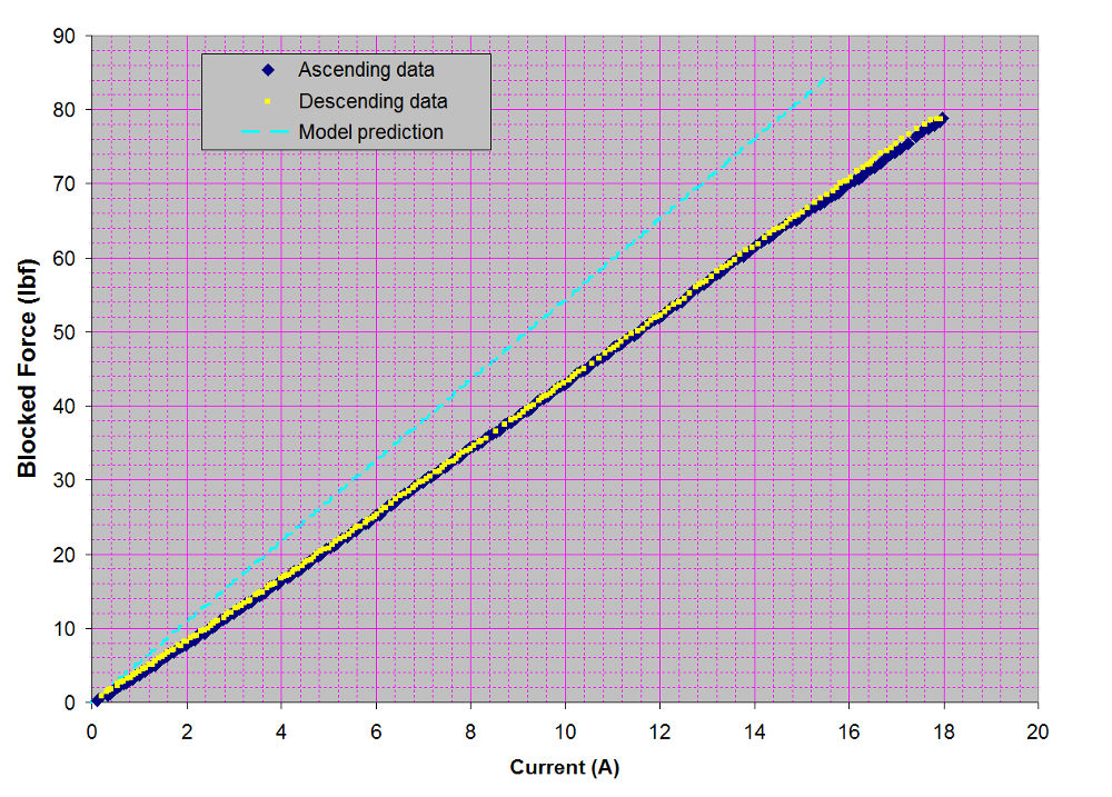
This plot (above) shows the linearity of the actuator blocked force output versus drive current. The force is measured at the center of the actuation distance. The drive current was limited to 18A because that is the limit of the power supply. Notice that the measured force deviates from the model prediction. Given time we will rebuild the model with the coil manufacturing changes to determine how accurately the actual device performance can be predicted.
To measure the linearity of the actuator over the actuation distance we implemented a test with a moveable load cell. The results are pictured below.
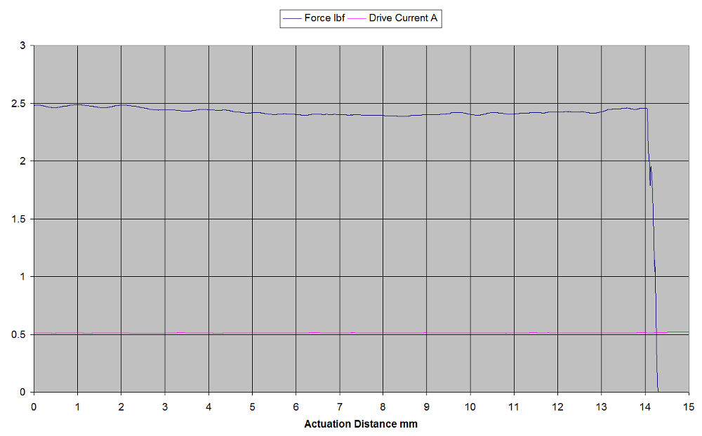
As you can see, the force over the actuation distance remains fairly constant. The small variations in the force waveform are due to the fact that the linear slide that the load cell was mounted on was driven manually. The actuator on the other hand, when driven with a constant DC input, as in this case, wants to move at a constant velocity across the actuation distance. The overall response which has a slight dip at the center, is the force / distance response of the actuator for a fixed DC drive.
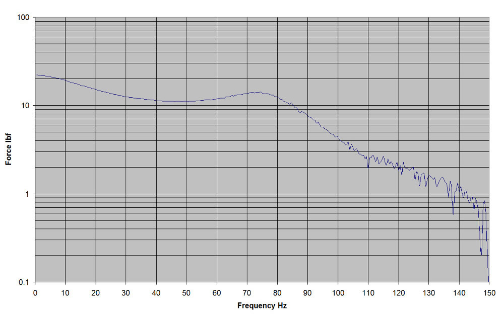
The graph above shows the frequency response of the 3 inch actuator. The model prediction was 80Hz and from this result we can safely consider 85Hz to be within the frequency range of the device.
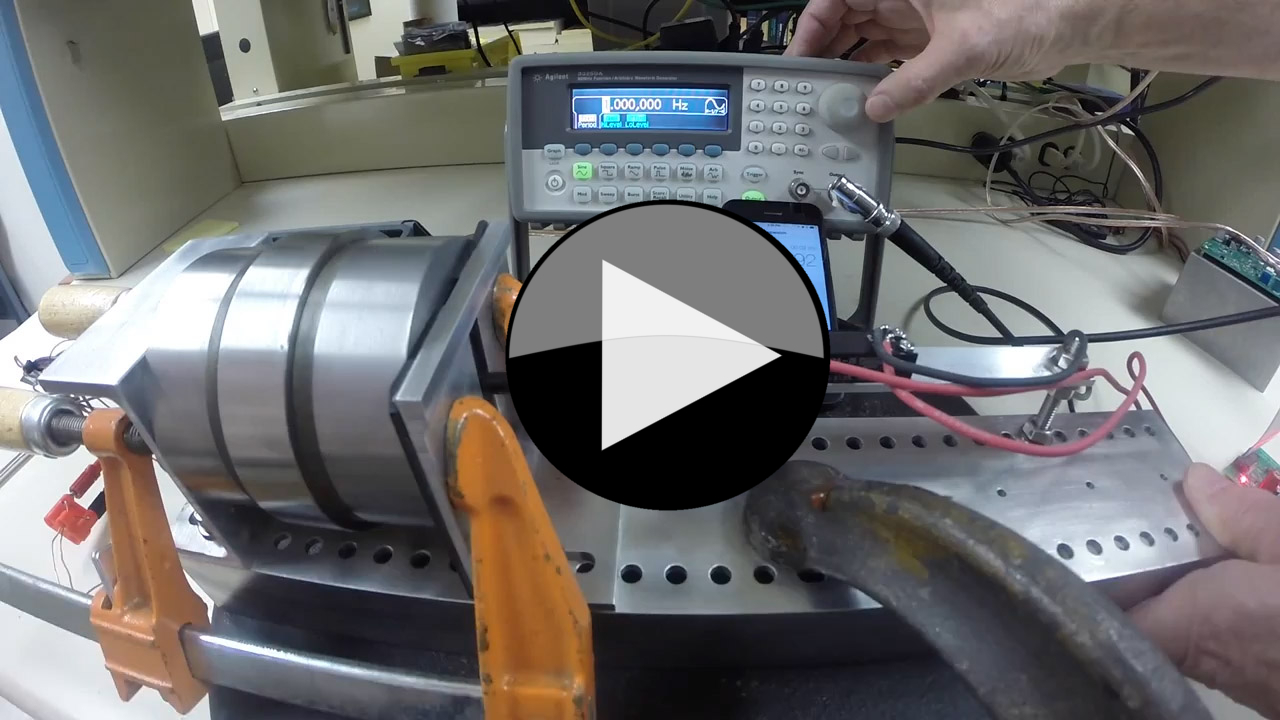
Here is a video of this actuator being driven at different frequencies with Sine and Square wave signals through a PID controller. Note the clamps holding the actuator to a stack of 50lb weights, clamped to the bench.
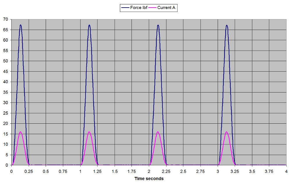
The next graph (below) shows the impulse response of the 3 inch actuator. This test was done while driving the actuator into a 146lbf/inch spring that was pressing against a load cell. This test setup is better at approximating a typical application in that the actuator is moving while applying a load instead of simply measuring a blocked force response. The rate and wave shape was chosen to approximate a walking gate force profile with intervening periods of unpowered free swing.
Applications:
This device can be used as a robotic actuator with high force yet compliant actuation allowing enhanced human / machine interaction. Applied as a walking gate actuation device it can quickly and seamlessly transition from full force to total compliance. The inherent variable compliance, or variable stiffness nature of this actuator technology also makes it well suited for robotic handling of delicate objects since the force can be linearly and rapidly controlled from zero to maximum at any point in the actuation distance.
Enhanced human machine interfacing can be achieved by using this device for haptic feedback applications. Because this device basically behaves as a high speed electrically variable spring with constant force across the displacement distance, it would allow the user to experience the texture of whatever the controlled robot is touching by feeding back the robot’s force or touch sensor data to the human interface force feedback actuator. This would effectively create a variable impedance force feedback system.
Hydraulic, pneumatic, or any other type of flow valve, can be controlled with this actuator. The distance of actuation, force and linearity can be tailored to the requirements of the valve, and since the actuator is bi-directional it does not require return springs or dual devices as would be required if solenoid technology was employed. Hydraulic valve chip shear can be easily handled by this actuator technology because it is also capable of very high impulse forces at any point along the actuation distance. This actuator is also capable of high frequency operation, much higher than solenoids, which could raise the overall control frequency response of a hydraulic or pneumatic actuation system.